


Boat Battery Switch Wiring Guide for DIY Boaters
A boat battery switch is defined as an electrical control device that lets you select, isolate, or combine onboard batteries to manage your vessel’s power safely. Every marine electrical system depends on this switch to protect the engine start battery, distribute charging current, and cut power when the boat sits idle. Getting the wiring right is not optional. A miswired switch can drain both batteries, damage your alternator, or create a fire hazard. This boat battery switch wiring guide covers every step from component selection through final hookup, following 2026 ABYC E-11 standards throughout.
What are the essential components and tools for wiring a marine battery switch?
The right materials determine whether your installation lasts one season or ten. Marine environments attack every connection with salt, humidity, and vibration. Standard automotive wire corrodes within months in that environment. Tinned copper wire is the only acceptable choice for marine DC wiring. The tinning process coats each strand with a thin layer of solder alloy, blocking oxidation at the point where corrosion starts.
Wire gauge is the next critical decision. Voltage drop is the primary factor for sizing marine DC wiring, and ABYC tables set a 3% maximum drop for charging and starting circuits. Ampacity alone does not tell you the right gauge. A cable run of 10 feet at 100 amps may need 2/0 AWG to stay within that 3% limit, even though a smaller gauge could technically carry the current.

Required components and typical wire gauges:
| Component | Spec / Gauge | Notes |
|---|---|---|
| Battery cables (short, under 3 ft) | 2 AWG | Engine start, high-current runs |
| Battery cables (medium, 3–10 ft) | 1/0 AWG | Typical dual battery setups |
| Battery cables (long, over 10 ft) | 2/0 AWG or larger | Verify with ABYC voltage drop table |
| Inline fuse or circuit breaker | Sized to cable ampacity | Within 7 inches of battery terminal |
| Marine battery switch | 300A continuous rating minimum | 1-2-BOTH-OFF type for dual battery |
| Tinned copper ring terminals | Match cable gauge | Crimp and heat-shrink sealed |
| Heat-shrink tubing | Adhesive-lined | Double-wall for bilge-area connections |
Tools you need before you start:
- Ratcheting cable crimper rated for marine lugs
- Wire stripper sized for 2 AWG through 2/0 AWG
- Insulated screwdrivers (flathead and Phillips)
- Heat gun for adhesive-lined heat shrink
- Multimeter for continuity and voltage checks
- Cable ties and split-loom conduit for routing
Pro Tip: Apply dielectric grease inside every ring terminal before crimping, then seal the entire connection with adhesive-lined heat-shrink tubing. This combination blocks moisture at the one point where corrosion is most destructive in harsh marine environments.
Fuse placement is where most DIY installations fail inspection. ABYC E-11 requires overcurrent protection within 7 inches of the battery positive terminal on every ungrounded conductor. That fuse or breaker protects the cable run, not the device at the end of it. Skipping it or moving it further down the run leaves a length of unprotected cable that can arc and ignite in a short circuit.
How to wire a basic 1-2-BOTH-OFF marine battery switch
The 1-2-BOTH-OFF switch is the standard for dual battery setups on single-engine boats. Position 1 connects Battery 1 to the electrical system. Position 2 connects Battery 2. BOTH connects both banks simultaneously. OFF isolates all batteries from the system. Each position serves a specific purpose, and using them correctly protects both your batteries and your alternator.
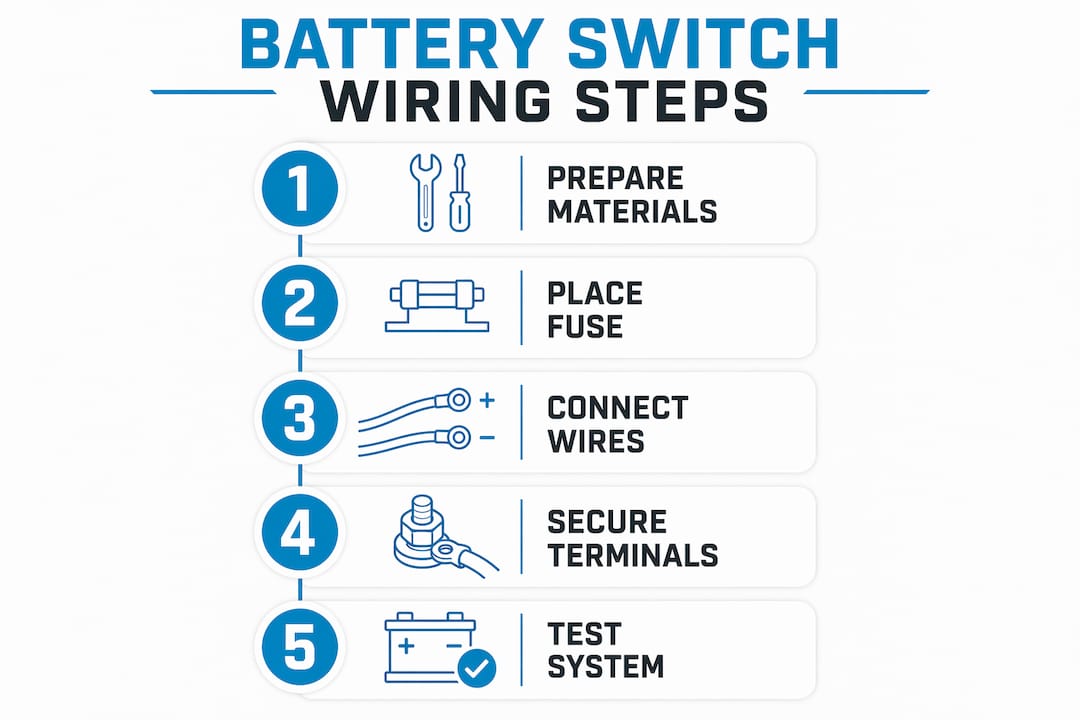
Follow these steps in order:
- Disconnect all batteries. Remove the negative cable from Battery 1 first, then Battery 2. Never work on a live marine electrical system.
- Mount the battery switch. Choose a location that is accessible but protected from accidental activation. A panel near the helm or inside a dedicated electrical compartment works well. Secure it with stainless steel hardware.
- Install the inline fuse on Battery 1 positive. Place it within 7 inches of the positive terminal. Use a fuse rated to the cable’s ampacity, not the load.
- Install the inline fuse on Battery 2 positive. Same rule applies. Both battery positives need independent protection.
- Run Battery 1 positive cable to Switch Terminal 1. Use the correct gauge for your cable length. Route the cable away from fuel lines and exhaust components. Secure it every 18 inches with cable ties or clamps.
- Run Battery 2 positive cable to Switch Terminal 2. Follow the same routing discipline. Keep positive and negative cables bundled together to minimize electromagnetic interference.
- Run the output cable from the switch common terminal to the engine starter and main bus. This is the cable that feeds all loads when the switch is in any active position. Size it for the full combined load.
- Connect all negative cables directly to a common negative bus bar. Negative cables do not pass through the battery switch. Run a heavy negative cable from each battery to the bus bar, then from the bus bar to the engine block.
- Add strain relief at every connection point. Secure cables within 2 inches of each terminal so vibration does not work the lug loose over time.
- Reconnect batteries and test each switch position with a multimeter before starting the engine.
Pro Tip: Wire safety-critical systems like your automatic bilge pump directly to the battery with its own inline fuse, bypassing the switch entirely. Bilge pumps must operate regardless of switch position, including when the switch is OFF.
The most dangerous mistake in this entire process is switching from position 1 to position 2 by rotating through OFF. Passing through OFF while the engine runs creates a momentary open circuit. That spike can destroy the alternator in an instant. Always switch directly from 1 to 2 without stopping at OFF.
For normal operation on a single-engine boat, start the engine on Battery 1, then switch to Battery 2 while underway to charge the house bank. Reserve the BOTH position for emergency starts only. Using BOTH routinely risks draining both batteries simultaneously.
What common wiring mistakes should you avoid?
Most marine electrical failures trace back to a small number of repeated errors. Recognizing them before you wire saves you from a dead boat at the worst possible moment.
Common mistakes and how to avoid them:
- Wrong fuse placement. Fuses placed more than 7 inches from the battery terminal leave cable unprotected. A short circuit in that unprotected run can start a fire before any breaker trips.
- Undersized cable gauge. Choosing wire by ampacity alone ignores voltage drop. An undersized cable runs hot, drops voltage at the starter, and shortens battery life.
- Ignoring negative cable sizing. Many boaters size positive cables correctly and use undersized negatives. The negative return path carries the same current and needs the same gauge.
- No labeling on switch positions. An unlabeled switch in an emergency leads to wrong choices. Label every position clearly with a permanent, waterproof label.
- Loose terminal connections. A lug that spins on its stud creates resistance, generates heat, and eventually fails. Torque every terminal to the manufacturer’s specification.
- Routing cables near heat sources. Cables run near exhaust manifolds or engine risers degrade quickly. Use heat-resistant loom and maintain clearance from any heat source.
Switching the battery selector to OFF while the engine is running will instantly damage the alternator due to voltage spikes. Always shut the engine down before switching to OFF, and always switch directly between positions 1 and 2 when the engine is running.
Pro Tip: After completing the installation, use a multimeter to measure voltage at the starter terminal with the engine cranking. A reading below 9.6V under load signals a wiring problem, usually an undersized cable or a poor connection.
Troubleshooting a switch installation that does not perform correctly follows a logical sequence. Check voltage at the battery first, then at the switch output terminal, then at the load. Each measurement narrows the fault to a specific cable run or connection. A voltage drop greater than 0.5V across any single connection point indicates a bad crimp or a corroded terminal.
How do dual circuit and advanced battery switch systems work?
Standard 1-2-BOTH-OFF switches require the operator to manage battery selection manually. That works well when the operator knows the rules. Dual circuit battery switches offer fail-safe battery isolation with automatic or manual combining, reducing the chance of user error and protecting the start battery from accidental drain.
The core difference is how each system handles battery combining. A manual switch depends entirely on the operator choosing the right position at the right time. A dual circuit system with automatic combining uses a voltage-sensing relay to connect the house bank to the start battery only when the alternator is charging. When the engine stops, the relay opens and the two banks separate automatically.
| Feature | Manual 1-2-BOTH-OFF switch | Dual circuit / automatic system |
|---|---|---|
| Battery isolation | Manual, operator-dependent | Automatic, voltage-sensing |
| Risk of draining start battery | Present if BOTH used routinely | Minimized by automatic separation |
| Alternator protection | Requires operator discipline | Built into relay logic |
| Installation complexity | Low | Moderate |
| Best for | Simple setups, experienced operators | Larger boats, multiple loads |
| Cost | Lower | Higher upfront, lower risk |
Smart monitoring upgrades pair well with either switch type. A battery monitor installed on the negative shunt gives you real-time state of charge, voltage, and current draw for each bank. That data tells you exactly when to switch banks and whether your alternator is charging correctly. For boats with complex electrical systems, that visibility is worth more than any single component upgrade.
Fusing both sides of the battery switch when an alternator connects to the system is a requirement, not a suggestion. An unfused alternator connection can feed a short circuit with enough current to cause a fire before any downstream breaker responds. This applies to both manual and automatic switch configurations.
For boaters planning a full marine battery bank setup, dual circuit systems paired with LiFePO4 batteries deliver the most reliable combination of automatic protection and long cycle life. The chemistry and the switch logic work together to keep the start battery full and the house bank available for extended use.
Key Takeaways
Correct marine battery switch wiring requires ABYC E-11-compliant fuse placement, tinned copper cable sized by voltage drop, and strict switch operating discipline to protect both batteries and the alternator.
| Point | Details |
|---|---|
| Fuse within 7 inches | Place overcurrent protection within 7 inches of every battery positive terminal per ABYC E-11. |
| Size wire by voltage drop | Use ABYC voltage drop tables, not ampacity alone, to select the correct cable gauge. |
| Never switch through OFF | Switch directly between positions 1 and 2 while the engine runs to avoid alternator damage. |
| Wire bilge pumps to battery directly | Safety-critical loads must bypass the switch and connect directly to the battery with an inline fuse. |
| Label and secure everything | Clear labels and proper strain relief prevent misoperation and connection failures from vibration. |
What I’ve learned from years of watching boaters wire switches wrong
The single most underestimated step in any marine battery switch installation is fuse placement. Every experienced marine electrician knows the 7-inch rule. Yet I see installations constantly where the fuse sits 18 or 24 inches from the terminal, tucked somewhere “convenient.” That gap is a fire waiting for a short circuit to ignite it. ABYC E-11 is not a suggestion. It is the line between a safe boat and a burned one.
The second thing I tell every boater who asks about this is to label the switch before they ever connect a wire. Not after. Before. When you label first, you wire with intention. You think about what each position does and what happens if someone unfamiliar with the boat hits the wrong position in an emergency. Clear, waterproof labels cost almost nothing and prevent expensive mistakes.
I also advocate strongly for adding a battery monitor to any dual battery setup. The switch tells you which bank is connected. The monitor tells you whether that bank actually has enough charge to start the engine. Those are two different pieces of information, and you need both. A LiFePO4 marine battery paired with a quality monitor gives you accurate state-of-charge data that AGM chemistry cannot match.
Finally, do not skip the corrosion prevention steps because the connections look clean today. Marine environments are relentless. Dielectric grease, adhesive-lined heat shrink, and tinned terminals are cheap insurance against a failure that will happen at the worst possible time, miles from the dock.
— Donald
Bansheebatteries marine power for your next installation
Wiring a battery switch correctly is only half the equation. The battery behind that switch determines how much reliable power your system actually delivers.

Bansheebatteries designs lithium marine batteries built specifically for the demands of marine electrical systems, including dual battery setups wired exactly as described in this guide. Their LiFePO4 batteries carry a 5-year warranty and deliver consistent voltage across the full discharge cycle, which means your electronics and starter get full power right up to the end of the charge. Bansheebatteries also offers marine-grade battery chargers with overcharge and short-circuit protection to keep your banks healthy between trips. Their team is available to help you match the right battery to your specific wiring configuration.
FAQ
What is the role of a battery switch on a vessel?
A marine battery switch controls which battery or battery bank powers the vessel’s electrical system. It lets you isolate, select, or combine banks for starting, charging, and load management.
Where should the fuse go in a boat battery switch wiring setup?
The fuse or circuit breaker must sit within 7 inches of the battery positive terminal on every unprotected conductor, per ABYC E-11. This placement protects the full cable run from short-circuit fires.
Can I switch from battery 1 to battery 2 while the engine is running?
Yes, but you must switch directly from 1 to 2 without passing through OFF. Rotating through the OFF position while the engine runs creates a voltage spike that can destroy the alternator immediately.
What loads should bypass the battery switch entirely?
Automatic bilge pumps must wire directly to the battery with an inline fuse, bypassing the switch. These safety-critical devices need to operate even when the switch is in the OFF position.
What is the difference between a manual switch and a dual circuit system?
A manual 1-2-BOTH-OFF switch requires the operator to manage battery selection. A dual circuit system uses a voltage-sensing relay to combine and separate banks automatically, reducing user error and protecting the start battery.