


Marine Battery Installation Checklist for Boat Owners
Here is the short version: inspect the battery, mount it securely above the bilge line, route tinned-copper cable along the actual path (not straight-line), place a fuse within 7 inches of the positive terminal per ABYC E-11 §11.10.1.5; starter cables allow up to 40 inches under the same standard. Connect positive first, then negative last, verify charger compatibility, and load-test before you leave the dock.
Essential install steps in order:
- Inspect chemistry, Ah rating, voltage, and physical condition before touching terminals
- PPE on — safety glasses and acid-resistant gloves minimum; face shield for flooded cells
- Mount in an approved battery box or tray, secured with stainless hold-downs above the bilge waterline
- Route cables along the actual path; measure positive plus negative run together
- Fuse within 7 inches of the positive terminal — use a Class-T fuse for LiFePO4 or high-AIC circuits
- Connect positive first, negative last during installation; reverse for removal
- Verify charger compatibility — LiFePO4 requires a lithium-profile charger or DC-DC converter
- Load-test and confirm voltage drop stays under 3% on critical circuits
For LiFePO4 installs, keep the battery near 50% state-of-charge (SOC) during handling to limit energy release if an accidental short occurs. Bansheebatteries offers both AGM and LiFePO4 marine batteries with multi-year warranties and detailed setup guidance for each chemistry.
Pro Tip: Measure your cable run by tracing the actual routed path around bulkheads and engine mounts, not the straight-line distance. Measuring shortest distance instead of the routed length is the single most common cause of voltage drop failures, even when ampacity looks legal on paper.
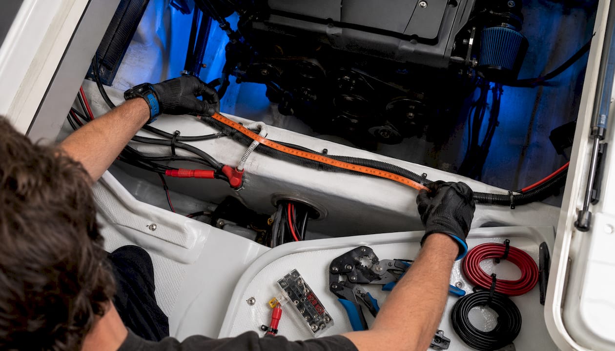
Table of Contents
- What tools and materials do you need before starting?
- Pre-install inspections: what to verify before you touch the terminals
- Where and how should you mount the battery on a boat?
- How do you size cables, route them, and place fuses correctly?
- What is the correct connection sequence and how tight should terminals be?
- Charging system compatibility and authoritative safety rules
- How do you test and commission the battery after installation?
- What does a post-install maintenance schedule look like?
- Quick troubleshooting for no-crank, parasitic draw, and voltage drop
- PPE requirements and safe handling for marine battery work
- How to disconnect and remove an old battery safely
- How should you dispose of an old marine battery?
- Hydrogen gas and explosion risk: what you need to know
- How do you verify marine electrical standards compliance?
- How do grounding and bonding work in a marine electrical system?
- Key Takeaways
- The five installation mistakes that actually sink boats
- Authoritative sources and where to read next
What tools and materials do you need before starting?
Gather everything before you touch the battery. Stopping mid-install to hunt for a crimper or the right fuse size is how mistakes happen.
Tools:
- Digital multimeter and clamp meter
- Ratcheting marine crimper (not an auto-parts store crimper)
- Heat gun for adhesive-lined heat shrink
- Torque wrench
- Wire strippers rated for your gauge
- Drill with bits for mounting
- Wire fish or pull tool for tight runs
Parts:
- Marine tinned-copper wire sized per routed length
- Ring terminals and adhesive-lined heat shrink
- Class-T or ANL fuse holders and correctly rated fuses
- Approved battery box or tray with stainless hold-down hardware
- Dielectric grease
- Terminal boots/covers
PPE:
- Safety glasses (non-negotiable)
- Acid-resistant gloves
- Face shield when handling flooded (wet-cell) batteries
- A Class B/C fire extinguisher within reach on deck
| Run length (round trip) | Typical current | Suggested minimum AWG |
|---|---|---|
| Under 10 ft | 20A | 12 AWG |
| 10–20 ft | 20A | 10 AWG |
| 10–20 ft | 50A | 6 AWG |
| 20 ft | 100A | 1/0 AWG |
Based on ABYC E-11 for 3% voltage drop on 12V critical circuits. Always use marine-grade tinned copper.
Pro Tip: Pack spare fuse sizes and a temporary insulated terminal cover. During commissioning, you may need to swap fuses while the circuit is live, and a bare positive terminal is a short waiting to happen.
Pre-install inspections: what to verify before you touch the terminals
Start with identification. Know what you have before you connect anything.
Inspection checklist:
- Confirm chemistry: flooded lead-acid, AGM, or LiFePO4
- Note Ah rating, nominal voltage, and BMS parameters for lithium
- Check for cracks, bulging, leaks, corrosion, or loose posts
- Measure open-circuit voltage and estimate SOC by chemistry
- Confirm manufacturer torque specs and mounting instructions are in hand
For a 12V flooded or AGM battery, a resting open-circuit voltage of roughly 12.6V indicates a full charge; below 12.4V suggests partial discharge. A 12V LiFePO4 at rest typically reads 13.2–13.3V when full and around 12.8–13.0V at 50% SOC. These are reference points, not absolutes — always cross-check with the manufacturer’s chart.
Keep flooded batteries upright and in a ventilated space during inspection. For lithium, handling at ~50% SOC significantly reduces stored energy during a potential accidental short. If the battery arrives fully charged, consider partially discharging it before making final connections.
Use Bansheebatteries’ marine battery size guide to cross-check Ah ratings against your daily load before committing to an install.
Pro Tip: Write the manufacturer’s terminal torque value on a piece of tape and stick it to the battery tray. You will need it again at commissioning and at every annual survey.
Where and how should you mount the battery on a boat?
The battery goes at the lowest practical point above the bilge waterline, in a dry, well-ventilated compartment, away from fuel lines and ignition sources. That is the rule. Everything else is execution.
Mounting checklist:
- Dry-fit the tray before drilling anything
- Use stainless fasteners through a solid mounting surface (stringer, reinforced panel)
- Secure with an approved battery box and hold-down — an unsecured battery can slide and short in rough water
- Confirm overhead clearance for terminals and cables before tightening
- Label the circuit and battery number on the tray
- Orient for service access — you will need to read the terminals and check connections periodically
Ventilation rules differ by chemistry. Flooded batteries off-gas hydrogen during charging and require a vented enclosure with airflow to the outside. Sealed AGM and LiFePO4 batteries produce far less gas under normal conditions, but you still want to avoid enclosed heat buildup, especially in engine compartments.
Pro Tip: Place closed-cell foam isolation pads between the battery tray and the mounting surface. They absorb vibration that would otherwise work terminal connections loose over a season.
How do you size cables, route them, and place fuses correctly?
Cable sizing and fuse placement are where most DIY installs go wrong. Get these right and the rest of the job is straightforward.
Wiring checklist:
- Measure the full routed run: positive from battery to load, plus negative back to ground
- Size wire for ampacity first, then check voltage drop — keep critical circuits under 3%
- Place overcurrent protection within 7 inches of the positive terminal (ABYC E-11 §11.10.1.5); starter cables get a 40-inch exception
- Use Class-T fuses for lithium and high-AIC circuits — standard ANL fuses can weld shut at the fault currents a lithium bank produces (8,000–12,000 A)
- Size fuses to protect the conductor, not the device; apply roughly 20% headroom above continuous current
- Secure wiring every 18 inches; keep DC runs at least 12 inches from AC wiring
- Route through bulkheads and hull penetrations with grommets; protect against chafe at every sharp edge
| Circuit | Continuous amps | Round-trip length | Recommended AWG |
|---|---|---|---|
| Accessory (short) | 20A | Under 10 ft | 12 AWG |
| House loads (medium) | 50A | 10–20 ft | 6 AWG |
| Starter/main (long) | 100A | 20 ft | 1/0 AWG |
For a boat battery switch wiring setup with parallel banks, run equal-length positive cables from each battery to the bus bar. Unequal lengths create resistance imbalance and uneven charging.
Pro Tip: On parallel banks, plan equal-length positive runs to the bus. A 6-inch difference in cable length creates measurable imbalance at high charge currents.
What is the correct connection sequence and how tight should terminals be?
Removal sequence: disconnect negative first, then positive. This breaks the circuit before you touch the live terminal.
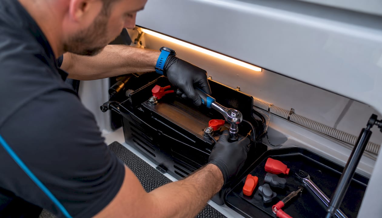
Installation sequence: connect positive first, then negative last. Connecting negative last means the final connection is to ground — if the wrench slips, it shorts to the hull or engine block rather than across the live positive terminal.
Both sequences exist for the same reason: keep the live terminal isolated until the very last moment.
Connection checklist:
- Torque to manufacturer specifications — record the value; do not guess
- Common stud sizes run from 5/16-inch to 3/8-inch; torque ranges vary by terminal design, so use the spec sheet, not a rule of thumb
- Apply dielectric grease to bolt-on ring terminals before tightening
- Use adhesive-lined heat shrink over every crimped connector
- Install insulated boots or covers over positive terminals immediately after connection
A loose terminal is a resistance point. Resistance means heat. Heat in a marine environment means corrosion, arcing, and eventually a fire. Torque it correctly once and check it annually.
Pro Tip: Use a torque wrench for final connections and write the torque value on a small label inside the battery compartment. Marine surveyors will ask, and you will want the answer.
Charging system compatibility and authoritative safety rules
Verify charger and alternator compatibility before you commission any lithium install. This step is skipped more often than any other, and it is the one most likely to destroy a new battery.
LiFePO4 can accept higher charge currents than lead-acid batteries, often up to the full rated capacity, far more than a conventional alternator or lead-acid charger expects to deliver. Without a lithium-compatible smart charger or a DC-DC converter, a standard alternator will run at full output continuously until it overheats. Lead-acid and AGM batteries typically accept 25–50% of capacity as charge current, so existing charging systems are sized for that load.
Charging compatibility checklist:
- Confirm charger has a lithium (LiFePO4) profile or user-programmable voltage settings
- Add a DC-DC charger or lithium-compatible alternator regulator if upgrading from lead-acid
- Verify BMS-controlled contactor or Class-T fuse is in place for high-AIC protection
- Set absorption voltage to manufacturer spec (typically 14.2–14.6V for 12V LiFePO4)
- Disable temperature compensation on lithium chargers — it is designed for lead-acid and will overcharge lithium cells
- Keep critical circuit voltage drop under 3%; single-connection drop under 0.1V
ABYC E-11 fuse placement within 7 inches of the positive terminal matters here too. The shorter the unprotected conductor, the less wire is exposed to a fault before the fuse interrupts it.
Pro Tip: Before the first charge on a new LiFePO4 bank, isolate the battery with its BMS connected, then run a controlled bulk charge while monitoring temperature and current draw. Any cell imbalance or BMS fault will show up here, not 20 miles offshore.
How do you test and commission the battery after installation?
Testing is not optional. It is how you confirm the install is correct before the boat leaves the dock.
- Reconnect and torque all terminals; verify all fuses are installed and rated correctly
- Measure open-circuit voltage at the battery terminals and confirm it matches expected SOC
- Wait 10–15 minutes after any recent charge to let surface charge dissipate before reading resting voltage
- Measure voltage at the load end of a critical circuit — the difference from battery voltage is your actual voltage drop
- Check each connection point with the multimeter; acceptable single-connection drop is under 0.1V, total circuit under 0.5V for critical loads
- Crank the engine and watch battery voltage; it should not collapse below the manufacturer’s minimum cranking voltage
- Confirm the charger or alternator enters bulk stage and the charge current and voltage match the battery’s profile
- For LiFePO4, measure charge acceptance current and confirm the BMS is communicating normally
Record your baseline voltage, current draw, and voltage drop measurements. Write them on a label inside the battery compartment. When something changes six months from now, you will have a reference point.
Pro Tip: Keep a simple commissioning log — date, open-circuit voltage, voltage drop at key circuits, and charger profile confirmed. It takes five minutes and saves hours of troubleshooting later.
What does a post-install maintenance schedule look like?
Monthly:
- Visual inspection of terminals for corrosion or looseness
- Measure resting voltage and compare to baseline
- Check charger float or maintenance settings are active
Quarterly:
- Clean terminals with a baking soda solution if corrosion is present; dry thoroughly, reapply dielectric grease
- Inspect tray, hold-downs, and fasteners for movement or rust
- Check electrolyte level on flooded cells (distilled water only)
Annually:
- Full load test
- Inspect all cable runs for chafe, heat damage, or loose supports
- Verify fuse condition and replace any that show discoloration
| Interval | Action |
|---|---|
| Monthly | Visual inspection, resting voltage check, charger settings |
| Quarterly | Terminal cleaning, tray/fastener check, electrolyte level (flooded) |
| Annually | Load test, cable inspection, fuse condition, torque check |
Storage: Fully charge the battery, disconnect the negative terminal, and store in a cool dry location. Use a battery maintainer if shore power is available. LiFePO4 stores best at 50–60% SOC per manufacturer guidance — do not store it fully charged for months at a time.
Pro Tip: Keep a small service kit in the battery compartment: spare fuses in the correct ratings, a terminal boot, a strip of adhesive-lined heat shrink, and a small tube of dielectric grease. You will use it.
Quick troubleshooting for no-crank, parasitic draw, and voltage drop
No-crank: Check starter fuse condition first. Then measure battery voltage while cranking — if it drops below the manufacturer’s minimum, the battery is either discharged or failing. Confirm terminal torque before condemning the battery.
Parasitic draw: With all loads off, connect a clamp meter in series with the negative cable. Isolate circuits one by one until the draw drops. Common culprits are bilge pump float switches, stereo memory, and poorly wired accessories. For more diagnostic steps, Bansheebatteries covers battery charge retention issues in detail.
Excessive voltage drop: Measure voltage at the battery, then at the load. The difference is your drop. If it exceeds 3% of nominal voltage on a critical circuit, check each connection in the run for individual drop over 0.1V. A corroded ring terminal or undertorqued stud is usually the culprit.
Quick fixes: Retorque terminals to spec, reseal corroded connections, replace undersized wire, and swap in proper Class-T fuses where ANL fuses are installed on lithium circuits.
When to call a marine electrician: AC shore-power integration, high-current alternator regulator upgrades, and insurance or survey inspections on vessels over 26 feet are all situations where a certified ABYC technician earns their fee.
PPE requirements and safe handling for marine battery work
Safety glasses are the floor, not the ceiling. A 12V battery can deliver hundreds of amps into a short circuit — enough to vaporize a wrench, spray molten metal, and ignite hydrogen gas in the same instant.
Required PPE by task:
- All battery work: safety glasses, acid-resistant nitrile or rubber gloves
- Flooded (wet-cell) batteries: add a face shield; sulfuric acid splashes during tipping or overfilling
- High-current connections (100A+): insulated tools rated for the voltage; keep one hand clear of the circuit
- Any work near a charging battery: no open flames, no sparks, no smoking within the compartment
Remove metal jewelry before starting. A ring or watch across battery terminals produces a severe burn in under a second. Keep a bucket of water and baking soda nearby when working with flooded cells to neutralize acid spills immediately.
How to disconnect and remove an old battery safely
Work in this order and you will not create a short or an arc.
- Turn off all electrical loads and the ignition
- Locate the negative terminal and loosen the cable clamp first — use an insulated wrench
- Tuck the negative cable away from the terminal so it cannot accidentally contact metal
- Loosen and remove the positive cable; cover the terminal immediately with an insulated boot
- Remove hold-down hardware and lift the battery straight out — flooded batteries must stay upright
- Inspect the tray and compartment for corrosion, acid residue, or damaged wiring before installing the new battery
- Clean the tray with a baking soda solution, rinse, and dry completely
A flooded battery can weigh 50–70 lbs. Use a battery strap or lifting handle. Do not tilt it more than 45 degrees or you risk spilling electrolyte.
How should you dispose of an old marine battery?
Lead-acid batteries — flooded, AGM, and gel — are classified as hazardous waste and cannot go in household trash or a dumpster. The lead and sulfuric acid are both regulated under federal and state environmental law.
The simplest option: most auto parts retailers and marine dealers accept used lead-acid batteries for recycling at no charge. Call-2-Recycle and Earth911 both maintain searchable drop-off locators for the US. Many states require retailers who sell lead-acid batteries to accept returns.
LiFePO4 batteries contain lithium iron phosphate, which is less toxic than other lithium chemistries but still requires proper recycling. Check with your battery manufacturer for take-back programs. Bansheebatteries can direct you to appropriate recycling resources for their products.
Never puncture, incinerate, or submerge a battery of any chemistry. A punctured LiFePO4 cell can enter thermal runaway even without an external ignition source.
Hydrogen gas and explosion risk: what you need to know
Flooded lead-acid batteries produce hydrogen gas during charging, particularly during the absorption and equalization stages. Hydrogen is colorless, odorless, and ignites at concentrations as low as 4% by volume in air. A single spark from a tool, a switch, or a loose connection is enough.
Safety rules for flooded battery compartments:
- Never charge in an enclosed, unventilated space
- Vent the compartment to the outside before and during charging
- Do not connect or disconnect cables while the charger is active
- Install a hydrogen-rated vent fan if the compartment is below deck
- Keep all ignition sources — switches, relays, fuses — outside the battery compartment where possible
AGM and LiFePO4 batteries produce significantly less hydrogen under normal conditions, but a damaged or overcharged AGM cell can still off-gas. A LiFePO4 cell in thermal runaway produces different gases, including carbon monoxide. Treat any unusual smell or heat from any battery chemistry as an emergency: ventilate immediately and move away from the vessel.
How do you verify marine electrical standards compliance?
ABYC E-11 is the primary US standard for marine electrical systems. ISO 13297 covers similar ground for vessels built to international standards. Compliance is not just a paperwork exercise — insurance claims can be denied if non-compliant wiring is found after a fire or electrical failure.
Compliance checklist beyond fuse placement:
- All conductors sized per ABYC E-11 ampacity tables for the wire type and installation method
- Tinned copper wire throughout (non-tinned automotive wire corrodes rapidly in marine environments)
- All connections crimped with a ratcheting marine crimper and sealed with adhesive-lined heat shrink
- No solder as the sole means of connection (ABYC prohibits it)
- All circuits labeled at both ends with permanent wire markers
- Ignition-protected components in engine spaces (switches, relays, breakers)
- Shore-power connections compliant with ABYC A-28 and UL 1426 for boat wiring
For LiFePO4 installs, ABYC E-13 adds requirements for BMS functionality, thermal management, alternator compatibility, and a Class-T fuse on the main positive. Verify your install against both E-11 and E-13 before commissioning.
How do grounding and bonding work in a marine electrical system?
Grounding and bonding are two separate systems that serve different purposes, and confusing them is a common and sometimes dangerous mistake.
DC grounding is the return path for current in the 12V or 24V system. Every negative cable returns current to a common negative bus or directly to the battery negative terminal. A poor DC ground creates voltage drop, corrosion, and erratic instrument readings.
Bonding connects all underwater metal fittings (through-hulls, propeller shaft, rudder hardware) to a common bonding conductor, typically green-insulated wire. The bonding system equalizes potential between metal parts to prevent galvanic corrosion and provides a path for lightning dissipation. It does not carry operating current.
Grounding and bonding checklist:
- Confirm a single, low-resistance negative bus as the DC ground reference point
- Verify all negative returns connect to that bus, not to random hull fittings
- Inspect the bonding conductor for continuity from each underwater fitting to the bonding bus
- Check that the bonding system is isolated from the DC negative except at one intentional connection point (if your system uses that topology)
- On shore power, verify the AC safety ground is not creating a galvanic path through the bonding system — a galvanic isolator or isolation transformer may be required
A marine battery bank setup guide from Bansheebatteries covers grounding topology for both single and dual-bank configurations.
Key Takeaways
A safe marine battery install comes down to four rules: fuse close to the terminal, measure the real cable path, match the charger to the chemistry, and torque everything to spec.
| Point | Details |
|---|---|
| Fuse within 7 inches | ABYC E-11 §11.10 requires overcurrent protection within 7 inches of the positive terminal for general conductors and up to 40 inches for starter cables; use Class-T for lithium circuits. |
| Measure routed cable length | Voltage drop calculations require the full routed path (positive plus negative), not straight-line distance. |
| Verify charger compatibility | LiFePO4 requires a lithium-profile charger or DC-DC converter; a standard lead-acid charger will damage the bank. |
| Torque to manufacturer spec | Record torque values on a label in the compartment; check annually and after any rough-water season. |
| Keep LiFePO4 at around half charge during handling | Reduces stored energy during accidental shorts; a recommended precaution for high-current lithium installs. |
The five installation mistakes that actually sink boats
The conventional wisdom says “just follow the wiring diagram.” The diagram is fine. What sinks installs is the five things the diagram does not show.
Undersized ground returns are the most overlooked problem in marine electrical work. Installers size the positive conductor carefully, then run the negative return in whatever wire is left on the spool. The return carries the same current as the positive. An undersized ground creates voltage drop, heat, and corrosion at every connection in the return path.
Measuring straight-line distance instead of the routed cable path is the second most common error. A run that looks like 8 feet on a diagram is often 14 feet once you route around the engine, through a bulkhead, and along a stringer. That difference pushes a 12 AWG circuit into voltage-drop failure territory.
Skipping the fuse close to the battery because “there’s already a breaker at the panel” is a real conversation that happens on real boats. The breaker at the panel protects the panel. The fuse within 7 inches of the terminal protects the entire cable run between the battery and the panel — the section most likely to chafe, short, and start a fire.
Mixing chemistries in a parallel bank — one AGM and one LiFePO4, or two different-age AGMs — creates a charging mismatch that degrades both batteries faster than either would age alone. Match chemistry, age, and Ah rating in any parallel configuration.
Not updating the charging system for lithium is the mistake that costs the most money. When converting to LiFePO4, budget for a DC-DC converter or lithium-compatible alternator regulator as part of the installation cost, not as an optional upgrade. A standard alternator charging a lithium bank directly will run at full output until it fails. The LiFePO4 marine battery guide from Bansheebatteries walks through the specific upgrade path.
One thing worth emphasizing: measure voltage drop at commissioning with the actual load running, not just with a multimeter at rest. That is where most installs reveal their real problems — correct hardware, wrong cable length, marginal connections that only show up under load.
Authoritative sources and where to read next
- Marine Power Lab wiring guide — the most practical ABYC-aligned wiring reference available online; covers conductor sizing, fuse placement, and routing rules with real examples
- Marine Power Lab battery systems guide — sizing multipliers by chemistry, voltage-drop methodology, and Class-T fuse selection
- Practical Sailor LiFePO4 install guide — SOC handling precautions and commissioning steps for lithium systems
- West Marine battery box guide — hold-down hardware, tray sizing, and mounting surface requirements
- Bansheebatteries LiFePO4 marine battery collection — product selection with chemistry-specific specs and warranty details
- Bansheebatteries marine batteries landing page — AGM and lithium options with sizing guidance for common vessel types
- Bansheebatteries charging system types guide — alternator, DC-DC, shore charger, and solar compatibility explained for both chemistries
- Watercraft accessories guide for beginners — practical accessory and safety setup reference for smaller watercraft owners
This article is general information for educational purposes. Confirm current ABYC standards, local regulations, and manufacturer specifications with a certified marine electrician or the relevant primary source before completing your installation.