


ABYC Aligned Marine Battery Cable Size: Calculator Ready 55–150A Examples
Marine battery cable size comes down to three numbers: the continuous amp draw of the circuit, the round-trip length of the run (both cables, not just one), and how much voltage drop you can tolerate, usually 3% for critical circuits and 10% for everything else. Run those three through the ABYC E-11 tables or a validated calculator, then bump up one gauge if you’re anywhere near a boundary. Whatever gauge you land on, buy tinned, stranded cable rated to UL 1426, and mount the fuse within 7 inches of the battery terminal.
TL;DR:
- Measure the continuous amperage, round-trip cable length, and voltage drop target, then choose a wire gauge at least one size larger if near boundaries.
- Use marine-grade tinned, stranded cable rated to UL 1426 and mount the fuse within seven inches of the battery terminal for safety and longevity.
- Account for installation conditions such as bundling, high temperatures, and conduit runs, which require stepping up one gauge for proper heat dissipation.
- Always size your fuse to match or be less than the cable’s ampacity, and place it on the positive lead within seven inches of the battery.
- When in doubt, round up to the next gauge size, especially when your calculation hovers near a boundary, to ensure safety and performance.
Table of Contents
- What You Need to Measure Before Sizing Marine Battery Cable
- How to Calculate the Right Marine Battery Cable Size
- Marine Battery Cable Size Chart by Amps and Distance
- Why Marine-Grade Cable Matters More Than the Gauge Number
- Sizing and Placing Fuses to Protect Your Cable Runs
- Installing Marine Battery Cable the Right Way
- Diagnosing an Undersized or Failing Cable Run
- Banshee Batteries’ Take on Getting Marine Wiring Right
- Pairing New Cable With the Right Battery Upgrade
- Where to Verify These Numbers Yourself
- Sources
What You Need to Measure Before Sizing Marine Battery Cable
Guessing at cable gauge is how boats end up with melted insulation and mystery voltage drops at the helm. Before you touch a wire chart, gather four real numbers.
Continuous amperage. Pull this from the device’s spec plate or its installation manual, not from a rough guess based on horsepower or wattage. A trolling motor rated at 55 amps on high, for instance, needs to be sized for that draw sustained over time, not for a momentary surge. If the spec sheet is missing or you inherited the boat with unlabeled gear, a clamp meter on the positive lead under real load gives you the actual number, and that’s the one that matters for cable sizing, not the manufacturer’s optimistic “typical draw” figure.
Round-trip length. This trips up more DIY wiring jobs than anything else. If your battery sits 12 feet from your electronics panel, your circuit length isn’t 12 feet, it’s 24, because current has to travel out on the positive cable and back on the negative. Skipping this doubling step is the single most common input error in marine wire sizing, and it consistently leads people to a gauge that’s one or two sizes too thin. Measure the actual physical path the cable will follow, not a straight line, since wire routed around an engine block or through a bulkhead conduit often runs longer than it looks on paper.
Voltage drop target. ABYC splits this into two tiers. Critical circuits, things like bilge pumps, navigation lights, and engine controls, get a 3% ceiling. Non-critical circuits, like cabin lighting or a stereo, can tolerate up to 10%. The distinction matters more on lower-voltage systems: a 12V system loses a much larger percentage of usable voltage per volt of drop than a 24V system carrying the same current, so 12V boats need to be more conservative with cable sizing, especially on long runs to a bow-mounted trolling motor or an anchor windlass.
Installation conditions. The ampacity ratings on standard charts assume reasonable free-air conditions. Real installations rarely match that assumption.
- Bundling multiple cables together in a loom reduces each cable’s ability to shed heat, which lowers its effective ampacity.
- Engine room temperatures routinely exceed the ambient assumptions baked into standard charts, and heat is the enemy of both conductor and insulation life.
- Tight conduit runs with no airflow trap heat the same way bundling does.
- Any of these conditions is a reason to step up one gauge rather than sizing to the bare minimum on the chart.
Write these four numbers down before you open a calculator. Half the sizing mistakes on boats happen because someone skipped straight to “what gauge do I need” without nailing down what they’re actually feeding into the math.
How to Calculate the Right Marine Battery Cable Size
The workflow is the same whether you’re doing the math by hand or plugging numbers into an online tool. Feed in continuous amps, round-trip length, system voltage, and your voltage drop target, and the calculation returns a minimum AWG size.
Voltage drop works on a simple relationship: longer runs and higher currents both push more drop through a given gauge, while thicker copper (a lower AWG number) reduces resistance and therefore reduces drop. You don’t need to memorize the resistance-per-foot constants for copper, but understanding the relationship helps you sanity-check a calculator’s output. If you double the length of a run, you roughly double the voltage drop for that gauge, which usually means moving up one or two wire sizes to get back under your target percentage.
Here’s the practical sequence to run every time:
- Confirm continuous amperage from the device spec sheet or a clamp-meter reading under load.
- Measure one-way distance from battery to device, then double it for round-trip length.
- Choose your voltage drop target: 3% for critical circuits, 10% for non-critical.
- Run those three inputs through an ABYC-aligned calculator, such as Battery Skills’ cable size tool, or cross-reference the ABYC E-11 tables directly.
- Compare the ampacity-based minimum against the voltage-drop-based minimum, and use whichever gauge is thicker.
- Add a safety margin: step up one gauge, or add roughly 10% headroom, if the load might grow or the run passes through a hot engine bay.
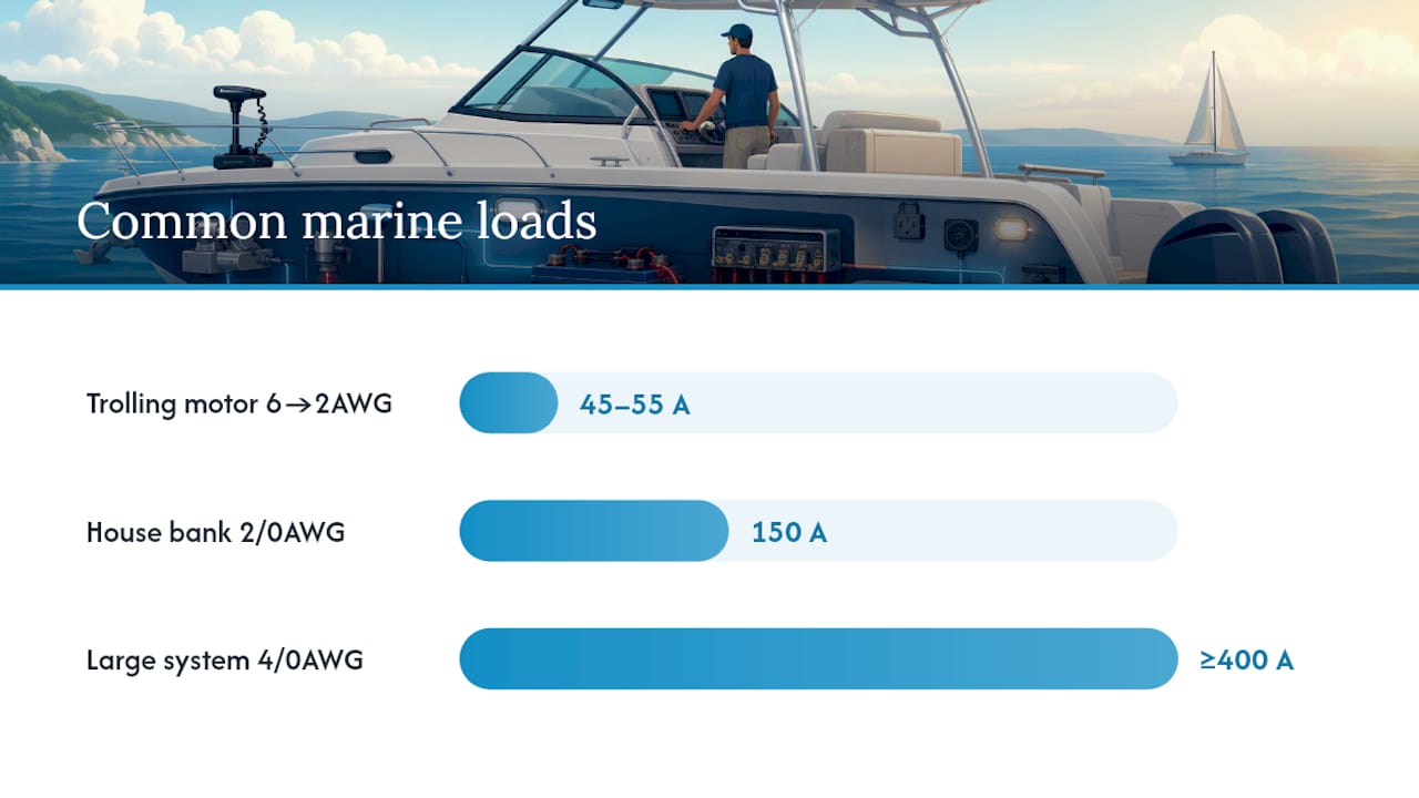
Example 1: Trolling motor, 24-foot round trip. A 55-amp trolling motor mounted at the bow with a battery in the stern often works out to a 12-foot one-way run, meaning 24 feet round trip. On a 12V system with a 10% voltage drop target (trolling motors are typically treated as non-critical for this purpose, though many owners size tighter), the ABYC-aligned math lands on 6 AWG. Tighten that to a 3% target, which some owners prefer for performance reasons since trolling motors lose noticeable thrust under voltage sag, and you’re looking at 2 AWG instead.
Example 2: House battery bank, 6-foot round trip, 150 amps. A short, heavy-draw circuit, like a battery bank feeding a 150-amp inverter load over a combined 6-foot round trip, needs a much thicker cable despite the short distance, because ampacity dominates the calculation at that current level. That circuit typically calls for 2/0 AWG, and installers commonly step up to the next size anyway for thermal headroom on inverter feeds that run hot for extended periods.
Statistic to remember: Marine cable sizes commonly range from 8 AWG for loads around 45 to 55 amps up to 4/0 AWG for systems drawing 400 amps or more. If your calculation lands outside that range in either direction, double-check your inputs before trusting the result.
One more rule that trips people up: the fuse doesn’t get sized to protect the device, it gets sized to protect the wire. Once you know the cable’s ampacity, the fuse rating has to sit at or below that number, never above it.
Marine Battery Cable Size Chart by Amps and Distance
The chart below covers common 12V loads and round-trip distances using ABYC-aligned voltage drop targets. Round-trip length is already doubled for you, so match your measured one-way distance to the nearest round-trip column.
| Continuous Amps | 24 ft Round Trip (3%) | 24 ft Round Trip (10%) | 48 ft Round Trip (3%) | 48 ft Round Trip (10%) | 100 ft Round Trip (3%) | 100 ft Round Trip (10%) |
|---|---|---|---|---|---|---|
| 55 A | 10 AWG | 12 AWG | 8 AWG | 10 AWG | 4 AWG | 8 AWG |
| 45 A | 8 AWG | 10 AWG | 4 AWG | 8 AWG | 2 AWG | 4 AWG |
| 70 A | 6 AWG | 8 AWG | 2 AWG | 6 AWG | 1/0 AWG | 2 AWG |
| 100 A | 4 AWG | 6 AWG | 1/0 AWG | 4 AWG | 2/0 AWG | 1/0 AWG |
| 150 A | 2 AWG | 4 AWG | 2/0 AWG | 2 AWG | 4/0 AWG | 2/0 AWG |
| 300 A+ | 4/0 AWG | 2/0 AWG | Dual 4/0 AWG | 4/0 AWG | Consult ABYC tables directly | Dual 4/0 AWG |
A few things worth flagging before you trust a lookup chart blindly:
- Starter circuits are a special case. Engine starter cables carry enormous but brief current, and they’re sized by a different logic than continuous-duty circuits like trolling motors or lighting. Follow the engine manufacturer’s cable spec for starter runs rather than a general-purpose chart.
- Inverter feeds deserve extra margin. A 2,000-watt inverter can pull well over 150 amps continuously on a 12V system, and that current runs hot for hours at a time, not seconds. Round up rather than down on any inverter circuit.
- Battery-bank interconnects follow the same amps-and-distance logic, but because the runs are usually short and thick, 1/0, 2/0, or 4/0 AWG cable is standard even over distances of just a few feet, since the total system current, not the distance, drives the sizing.
- The 300 A+ row is a floor, not a ceiling. At that current level, consult the ABYC tables directly or work with an installer, since a single 4/0 conductor may not be enough and parallel runs or busbars come into play.
If your exact amp draw or distance falls between two rows or columns, round up to the next size rather than interpolating down. The cost difference between one AWG size is small; the cost of an undersized cable that overheats under load is not.
Why Marine-Grade Cable Matters More Than the Gauge Number
Getting the AWG number right means nothing if the cable itself isn’t built for a boat. This is where a lot of otherwise careful DIY wiring jobs go wrong, because automotive cable looks nearly identical to marine cable on the shelf.
The standard to look for is UL 1426, which governs marine-grade battery and boat cable in the United States. Cable meeting this standard uses tinned, stranded copper conductors, not the bare copper strands common in automotive wire. The tin coating on each individual strand blocks the moisture and salt intrusion that would otherwise corrode bare copper from the inside out, long before any corrosion becomes visible on the outer jacket.
- Tinned strands resist saltwater corrosion that bare copper simply can’t handle over a multi-season lifespan.
- Insulation temperature ratings matter: look for cable rated 105°C dry and 75°C wet, since engine rooms and bilges routinely expose wiring to both heat and moisture at once.
- Higher strand counts improve flexibility for routing through tight bulkheads and around engine components without kinking or work-hardening the conductor.
- Pre-lugged cable saves time and reduces error on common lengths, and it’s worth the small premium if you’re not confident in your crimping technique.
Lug material matters too. Copper lugs with a proper tin plating pair correctly with tinned cable; mixing dissimilar metals at a connection point sets up galvanic corrosion right at the point where a bad connection does the most damage.
Sizing and Placing Fuses to Protect Your Cable Runs
A fuse exists to protect the wire, not the appliance on the other end of it. That single principle should drive every fuse decision on your boat, and it’s easy to get backwards if you’re used to automotive wiring conventions where fuses are chosen around the device.
The rule is straightforward: fuse rating should never exceed the wire’s ampacity. If your calculated cable size supports 100 amps continuous, your fuse needs to sit at or below that number, not at whatever the connected device happens to draw at its maximum. ABYC also requires the fuse to sit on the positive lead within about 7 inches of the battery terminal, unmeasured wire between the battery and the first fuse is unprotected wire, and that’s exactly the stretch most likely to short against a hull fitting or engine bracket during a rough crossing.
Different circuits call for different fuse types:
- ANL fuses handle high-amperage circuits like house battery banks and thick interconnects, typically anywhere from 100 to 500 amps.
- MEGA fuses cover a similar high-amp range and are common on marine and RV applications where space is tight.
- Class T fuses are the standard choice for inverter circuits because they clear a short circuit fast enough to protect against the extreme fault currents inverters can produce.
- Blade or ATO fuses remain appropriate for lower-amp accessory circuits like lighting and electronics.
A practical checklist for wiring in fuse protection: mount the fuse holder or busbar in a dry, accessible location near the battery, verify the holder itself is rated for the fuse’s amperage, and confirm every connection is torqued rather than just finger-tight. If you’re running a remote battery switch or breaker in addition to fuses, matching that breaker’s amp rating to your cable’s ampacity follows the exact same logic as fuse sizing. Skipping this step is one of the more common ways owners accidentally protect the device while leaving the wire exposed.
Installing Marine Battery Cable the Right Way
Correct gauge and the right cable spec still won’t save you from a bad installation. Routing, termination, and torque decisions determine whether that cable lasts one season or fifteen.
Routing. Keep runs as short and direct as practically possible, since every extra foot adds resistance and voltage drop. Secure cable every 18 inches or so with cushioned clamps to prevent chafe against fiberglass edges or metal brackets, a slow chafe-through against a moving hull component is a common cause of intermittent shorts that are maddening to diagnose. Where possible, separate power cables from sensitive signal wiring, like NMEA data lines, to avoid electrical noise interference.
Termination. Use the correct lug for the cable’s strand count and gauge, and match the lug’s bolt hole to the terminal it’s landing on. Crimping with a proper hydraulic or ratcheting crimper produces a far more reliable connection than a cheap hand tool, and soldering lugs onto marine cable is generally discouraged because solder can wick up into the strands and create a stiff point prone to fatigue cracking under vibration. Seal every crimped connection with adhesive-lined heat shrink to keep moisture out. Torque battery terminal connections to the hardware manufacturer’s spec, typically in the range of 70 to 90 inch-pounds for standard battery posts, since an under-torqued connection heats up under load and an over-torqued one can crack the terminal post.
Corrosion prevention and inspection. Apply a light coating of dielectric grease or anti-corrosion spray to terminal connections after they’re sealed. Inspect battery connections and cable runs at the start of each season, at minimum, and more often if you’re running in saltwater regularly.
- Check every terminal connection for looseness, green or white corrosion buildup, or heat discoloration on the insulation.
- Wiggle-test major connections by hand, a connection that shifts under light pressure needs to be redone.
- Look along the full cable run for chafe points, pinched sections, or insulation that’s cracked or brittle.
- Confirm the fuse holder and any busbars are dry, tight, and free of corrosion.
Pro Tip: Keep a small tube of dielectric grease and a torque wrench in your boat’s tool kit. A five-minute terminal check before you leave the dock catches the loose connection that would otherwise strand you at the fuel dock with a dead cranking battery.
Diagnosing an Undersized or Failing Cable Run
An undersized cable doesn’t usually fail outright on day one. It shows symptoms first, and catching them early keeps a wiring problem from turning into an electrical fire.
Watch for cables that feel warm or hot to the touch after running a load for a few minutes, sluggish engine cranking despite a healthy battery, and lights or electronics that dim noticeably when a high-draw device like a windlass or trolling motor kicks on. Any of those point to voltage drop that’s exceeding what the circuit can tolerate, and voltage drop, not raw ampacity, is what actually limits most marine circuits in real-world use.
A simple diagnostic sequence catches most problems:
- Clamp a meter on the cable while the device runs under normal load and compare the reading to the device’s rated draw; a significantly higher reading suggests a partial short or a failing component pulling extra current.
- Put a voltmeter at the device end of the circuit while it’s running and compare that reading to the battery’s resting voltage; a gap wider than your target percentage confirms excessive voltage drop.
- Feel the cable insulation along its length after sustained load; warm is a warning sign, hot enough to be uncomfortable to touch means stop using that circuit immediately.
If you find a genuinely undersized cable, a temporary fix like reducing load or shortening run time is fine to get you through a trip, but the permanent fix is replacing the cable with the correct gauge, not adding a second parallel run as a patch unless it’s engineered and fused correctly. Any cable showing melted insulation, a burnt smell, or scorched terminals is a stop-use-immediately situation that calls for full replacement before the circuit gets power again.
Banshee Batteries’ Take on Getting Marine Wiring Right
The pattern we see most often when customers describe electrical gremlins on their boats traces back to a cable that was sized for the wrong distance, or worse, never resized after a battery got moved to a new location. Our advice is simple: when the calculation puts you within one size of a boundary, round up. The cost difference between two adjacent gauges is a few dollars per foot; a callout for an electrical fire is not. We tell every customer to buy tinned marine-grade cable exclusively, torque every lug connection to spec rather than “snug,” and treat the fuse-near-the-battery rule as non-negotiable rather than optional.
If you’re rewiring a circuit anyway, it’s often the right moment to check whether your battery capacity still matches your electrical load, especially if you’ve added electronics since your last battery purchase. Our installation checklist covers the terminal and mounting details this guide didn’t have room for.
— Donald
Pairing New Cable With the Right Battery Upgrade
Rewiring a circuit is often the exact moment to reconsider the battery feeding it, especially if your boat’s electrical load has grown since the last battery went in. A battery that was adequate for a stock setup can struggle once you’ve added a bigger trolling motor, an inverter, or extra electronics, and undersized batteries stress the same connections you just spent an afternoon rewiring correctly.
Some manufacturers build Lithium (LiFePO4) marine batteries designed for the deep-cycle demands of trolling motors, house banks, and accessory circuits, often backed by warranties reflecting longevity. If your rewiring project includes adding a battery bank or replacing a tired AGM unit, the 12V 100Ah LiFePO4 battery is a common fit for trolling motor and off-grid marine setups. Pair either with a proper charger from our lineup to keep charge cycles healthy over a full season. Browse the full marine battery collection to find the capacity that matches the load you just wired for.
Where to Verify These Numbers Yourself
Cross-check anything in this guide against the primary sources marine electricians actually use.
- The ABYC E-11 standard is the governing reference for voltage drop limits and ampacity tables on recreational boats.
- Blue Sea Systems’ Circuit Wizard calculator is a widely used tool for running your own amps, distance, and voltage drop inputs against ABYC-aligned results.
- The round-trip length calculator at Goodkit is worth bookmarking specifically to double-check that you’ve doubled your one-way distance correctly.
Bookmark at least one of these before your next wiring project. Charts age poorly once you’ve forgotten which edition of ABYC they were built from, but a live calculator stays current.
Sources
- ABYC marine DC wiring guide - ToolGrit
- Electrical standards for marine wiring - Waytek Wire
- Boat battery cable size calculator - Battery Skills
- Marine wire gauge calculator (ABYC E-11) - Goodkit