


How a Lithium Battery Management System Works
A lithium battery management system continuously measures individual cell voltages, current, and temperature to estimate state of charge and state of health, balance cells, and disconnect the pack the moment conditions turn unsafe. That combination of monitoring, estimation, and protection is what keeps a lithium pack from overcharging, over-discharging, or sliding into thermal runaway. A charger alone can’t enforce those limits reliably, which is why operating a lithium cell without a BMS is genuinely dangerous rather than merely inadvisable.
Understanding how a lithium battery management system works means understanding six subsystems working in concert:
- Measurement — voltage, current, and temperature sensing across every cell
- State estimation — calculating SoC and SoH from raw measurements
- Balancing — equalizing cell voltages so the weakest cell doesn’t limit the whole pack
- Thermal management — keeping cells inside their safe operating window
- Protection — contactors, MOSFETs, and fault logic that disconnect the pack
- Communications — reporting pack status to chargers, vehicles, or cloud systems
Key Takeaways
A lithium battery management system works by pairing precise sensor data with estimation algorithms and hard protective limits, and the whole system is only as reliable as its weakest link, whether that’s sensor accuracy, balancing efficiency, or fault response time.
| Point | Details |
|---|---|
| Sensor accuracy sets the ceiling | Roughly ±5 mV per cell measurement accuracy limits how good any downstream SoC estimate can be. |
| ECM plus Kalman filter wins in production | This combination handles dynamic loads and sensor noise better than Coulomb counting alone. |
| Active balancing pays off at scale | Higher cell counts and higher power favor active topologies over passive bleed resistors. |
| Isolation checks are the most-skipped step | Commissioning without an independent isolation fault test leaves a hidden failure mode untested. |
| Thermal strategy shapes charge speed | Cooling method choice directly limits how fast a pack can charge without degrading. |
Table of Contents
- What Are the Primary Functions of a Lithium BMS?
- How Are Cell Voltage, Current, and Temperature Measured?
- Which State Estimation Method Fits Your Application?
- Passive vs. Active Cell Balancing: Which Do You Need?
- How Does Charging and Thermal Control Affect Battery Life?
- What Protection Mechanisms Prevent Battery Failures?
- How Does a BMS Communicate With Chargers and Vehicles?
- Centralized, Distributed, or Modular: Which BMS Architecture Wins?
- Practitioner Checklist for Commissioning a BMS
- Get a BMS-Protected Pack Instead of Building One
- The Gap Between Textbook BMS Design and What Actually Ships
- Frequently Asked Questions
- Sources
What Are the Primary Functions of a Lithium BMS?
Every production BMS runs the same core function set: monitoring, state estimation, balancing, power and thermal management, protection, and communications. MathWorks documents these as the standard architecture across automotive, marine, and stationary storage designs, and the distinction between the first two matters more than most engineers give it credit for.
Monitoring is direct measurement: a voltage reading, a current reading, a thermistor output. State estimation is derived: SoC, SoH, and state of power (SoP) get calculated from those raw measurements using a model, not read off a sensor directly. Confusing the two is a common rookie mistake. You can have perfect voltage sensors and still get garbage SoC numbers if the estimation algorithm underneath is weak.
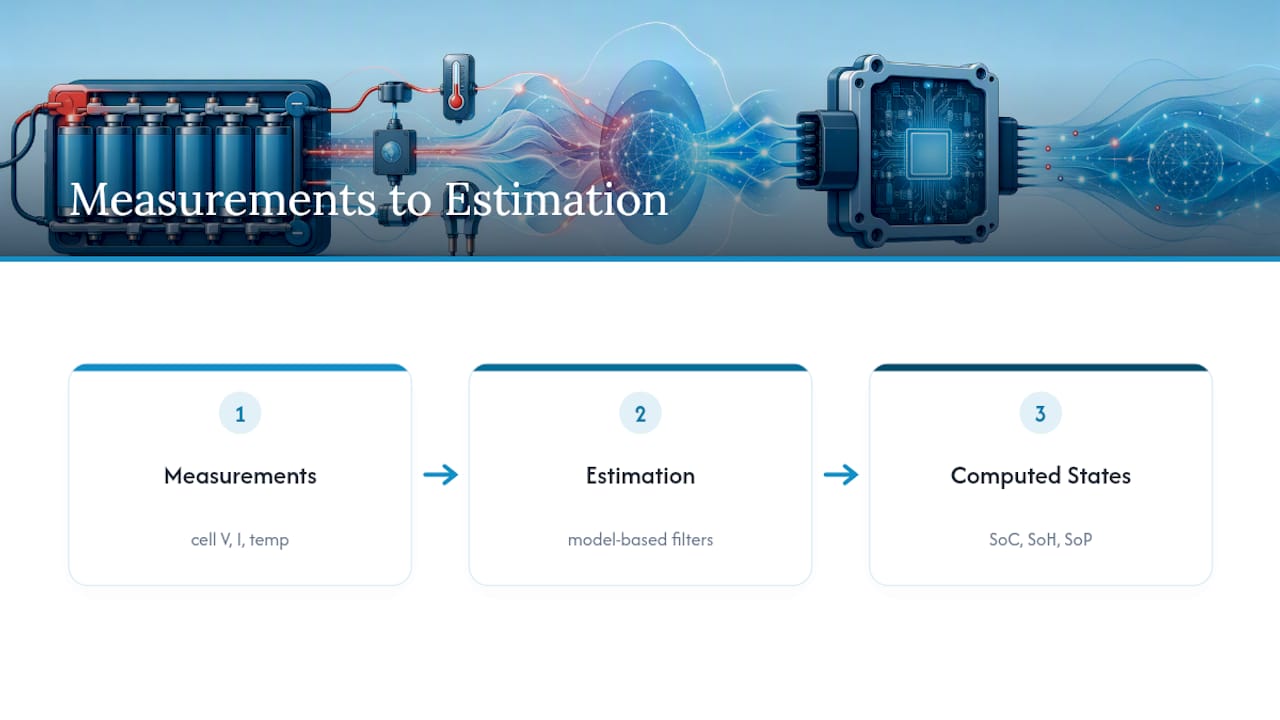
Each function maps to something the end user actually feels. Monitoring and protection deliver safe operation. Estimation and balancing deliver usable capacity, the difference between a pack that reports 100Ah on the label and one that actually delivers 95Ah in practice. Power and thermal management deliver charging speed without degrading the cells.
In an electric vehicle, protection response time is the priority. In a stationary battery energy storage system (BESS), SoH tracking over thousands of cycles matters more. In marine and powersports packs, the mix shifts toward thermal robustness and vibration tolerance, since these packs live in engine bays and hulls that get hot and get shaken.
Pro Tip: If you’re spec’ing a BMS for a marine or powersports application, check the thermal derating curve before the balancing spec. A pack that throttles charge current at 40°C ambient will frustrate users far more than a slightly slower balancing circuit.
How Are Cell Voltage, Current, and Temperature Measured?
An analog front end (AFE) IC sits between the cell stack and the microcontroller, reading each cell’s voltage and passing digitized values upstream over SPI or I²C. Modern AFEs handle 12 to 16 cells per chip, and stacking multiple AFEs is how packs scale into the hundreds of cells. Accuracy here isn’t cosmetic: production-grade designs target roughly ±5 mV per cell measurement, because a few millivolts of error at the AFE level translates into a meaningfully wrong SoC estimate downstream.
Current sensing splits into two camps. Shunt resistors are cheap and precise but dissipate power as heat and need to be sized for the pack’s peak current. Hall-effect sensors avoid that insertion loss and provide galvanic isolation, but they cost more and drift with temperature if not compensated.
- Shunt resistors: high accuracy, low cost, some power loss, need thermal compensation
- Hall-effect sensors: isolated, low insertion loss, higher cost, temperature drift
- Thermistors: placed between cells and at known hotspots, not just on the enclosure wall
- Isolation monitors: continuously check for leakage between the high-voltage bus and chassis ground
Thermistor placement is where a lot of designs quietly fail. A sensor bolted to the outside of a battery box tells you almost nothing about what the hottest cell in the middle of the stack is doing.
Which State Estimation Method Fits Your Application?
State of charge estimation is where the algorithm you pick determines how trustworthy the whole system feels to an end user. Four approaches dominate:
- Coulomb counting integrates current over time to track charge in and out. It’s computationally cheap but drifts because small sensor offsets accumulate, so most systems recalibrate against an open-circuit voltage (OCV) reading during rest periods or apply a capacity fudge factor learned over cycles.
- OCV lookup uses the relationship between rest voltage and SoC for a given chemistry. LiFePO4’s flat voltage curve through the middle of its range makes this method almost useless there, useful only near the top and bottom of charge, and it requires the pack to sit at rest long enough to settle.
- ECM plus Kalman filter pairs an equivalent-circuit model of the cell with a Kalman filter that continuously corrects the model against measured terminal voltage. This is the approach most production systems converge on because it handles load transients and sensor noise far better than Coulomb counting alone.
- Data-driven methods, typically neural networks trained on fleet data, learn SoC and SoH relationships directly from large datasets. They shine when you have cloud connectivity and thousands of packs feeding a shared model, but they’re overkill for a single-vehicle design.
A well-tuned ECM plus Kalman filter setup can hold SoC error within a couple of percentage points across a full drive cycle, provided the sensor accuracy upstream is solid. That’s the real payoff of the ±5 mV cell measurement standard: garbage sensor data caps how good any estimator downstream can perform, no matter how clever the filter math is.
Passive vs. Active Cell Balancing: Which Do You Need?
Cell imbalance is the silent capacity thief. If one cell in a series string sits lower than the rest, the whole pack’s usable capacity gets capped by that weakest link, even if every other cell has plenty of charge left. Balancing exists to close that gap.
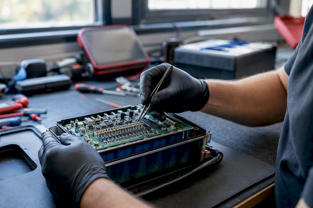
Balancing methods split into passive and active classes. Passive balancing bleeds excess energy from higher-voltage cells through a resistor until the pack levels out. It’s simple, cheap, and wastes energy as heat, which is fine for a 4-cell power tool pack and a real problem for a 96-cell EV pack losing meaningful capacity to bleed resistors every cycle.
Active balancing moves energy between cells instead of burning it off, using capacitors, inductors, or small transformers to shuttle charge from strong cells to weak ones. Higher cell counts and higher-power applications increasingly favor active topologies because the efficiency gain outweighs the added circuit complexity.
Deciding which to use comes down to four questions: How many cells are in series? What’s the duty cycle, frequent deep cycling or occasional top-offs? How much energy loss is tolerable? And can the budget absorb the extra bill-of-materials cost active balancing demands?
How Does Charging and Thermal Control Affect Battery Life?
Lithium cells charge in two phases: constant current (CC) until the cell hits its target voltage, then constant voltage (CV) while current tapers off. The BMS enforces both boundaries, capping current during CC and monitoring the taper during CV to know when to stop.
Temperature gates all of it. Charging a cold LiFePO4 cell too fast risks lithium plating that permanently reduces capacity, and a hot cell degrades faster under any load. Thermal management options range from passive air cooling to fans to liquid loops to direct immersion, each trading weight and complexity for better heat removal.
- Passive air: cheapest, works fine for low-power packs with generous surface area
- Active air (fans): moderate cost, handles moderate heat loads
- Liquid cooling: best heat transfer, adds weight, complexity, and pumping power
- Direct immersion: excellent uniformity, rare outside high-performance applications
Pro Tip: Don’t just chase peak cooling capacity. A liquid loop that moves too little coolant can leave uneven thermal gradients across the pack, which ages cells unevenly even though the average temperature looks fine on a dashboard.
What Protection Mechanisms Prevent Battery Failures?
Contactors and MOSFETs are the physical kill switches a BMS commands when something goes wrong, and precharge circuits exist to prevent the inrush current spike that happens when you connect a discharged capacitive load straight to a charged pack.
The BMS chooses between derating and hard disconnect depending on severity. A cell running a few degrees hot might just get a reduced current limit. A cell in overvoltage or a detected isolation fault gets an immediate contactor open, no negotiation.
- Overvoltage or undervoltage on any single cell
- Overcurrent beyond the pack’s rated limit
- Overtemperature at any monitored point
- Isolation faults between the HV bus and chassis
Automotive-grade designs build this fault logic against ISO 26262 functional safety requirements, which is also where that ±5 mV sensor accuracy standard carries real weight: a fault detection threshold is only as trustworthy as the measurement feeding it. Our engine management battery integration guide covers how these cutoffs interact with vehicle-side controls in more detail.
How Does a BMS Communicate With Chargers and Vehicles?
A BMS’s telemetry stream typically reports SoC, SoH, individual cell voltages, pack temperature, and any active fault codes. Where that data goes depends on the bus. CAN handles vehicle-level communication because it’s robust and standardized across automotive and marine electronics, while SPI and I²C handle short-range links between the AFE and the local microcontroller.
Fleet operators increasingly log this telemetry to the cloud, which turns individual pack data into predictive maintenance insight: spotting a cell degrading faster than its siblings before it becomes a field failure. A Bluetooth-enabled monitor with a shunt gives you a consumer-facing version of that same principle: live current and voltage data on your phone instead of a fleet dashboard. High-voltage systems also need isolation between the communication bus and the HV pack itself, since a communication fault should never become a safety fault. Home charging setups raise the same integration question at a smaller scale, and EV charger installation projects increasingly need to account for how the vehicle’s BMS negotiates charge rate with the charging hardware.
Centralized, Distributed, or Modular: Which BMS Architecture Wins?
A centralized architecture puts all the AFE and control logic on one board, wired directly to every cell. It’s cheaper and simpler for small packs but the wiring harness becomes unwieldy past a certain cell count, and one board failure takes down monitoring for the entire pack.
Distributed architectures split monitoring across slave boards near groups of cells, with a master coordinating over a local bus. This cuts harness complexity and improves fault isolation, since one slave failing doesn’t blind the whole system, but it adds bus latency and per-node cost.
- Centralized: simple, low cost, harness-heavy, single point of failure
- Distributed (master/slave): modular, better fault isolation, added bus complexity
- Module-based: easiest to repair and scale in production, ideal for larger packs
Small mobile devices and single-vehicle powersports packs lean centralized. Large EV and BESS installations lean distributed or modular because repairability and production scaling matter more than shaving a few dollars off the bill of materials.
Practitioner Checklist for Commissioning a BMS
Getting the algorithms right on paper doesn’t guarantee a pack behaves correctly on the bench. Commissioning is where theory meets wiring mistakes, and it’s worth treating as its own discipline rather than an afterthought.
- Calibrate voltage measurement first. Verify AFE readings against a known reference meter on every cell tap before trusting any SoC number.
- Run a full balancing test. Deliberately unbalance a test pack and confirm the balancing circuit brings cells back within tolerance in a reasonable time.
- Do a thermal soak test. Hold the pack at a sustained load and confirm thermistor readings track actual cell temperature, not just enclosure temperature.
- Verify isolation monitoring independently. Inject a known fault and confirm the BMS actually opens the contactor rather than just logging a warning.
The most common mistake we see is skipping the isolation check because everything else passed. A pack that measures voltage and current perfectly but never actually tests its isolation fault response is a pack waiting to fail in the field. Vendor development kits, like the reference designs STMicroelectronics documents for BMS prototyping, can shortcut a lot of this validation work if you’re building from scratch.
Pro Tip: Route thermistor wiring away from high-current cables. Induced noise on a temperature line can produce readings that look plausible but are quietly wrong, which is a hard bug to catch after the fact.
At Bansheebatteries, every LiFePO4 pack we build ships with BMS protection already commissioned against this exact checklist, so the calibration work is done before it ever reaches a customer’s boat or bike.
Get a BMS-Protected Pack Instead of Building One
Everything above explains how the electronics work, but building a reliable BMS from discrete components takes real engineering time, test equipment, and a willingness to get isolation faults wrong at least once before you get them right. Bansheebatteries builds that protection in at the factory. Our lithium marine batteries and powersport lithium batteries ship with balancing, thermal protection, and fault detection already calibrated, backed by a 5-year warranty on lithium marine packs. If you’re weighing a DIY build against a finished pack, browse the full lineup at Bansheebatteries before you order parts.
The Gap Between Textbook BMS Design and What Actually Ships
Most technical content on this topic treats Kalman filters and Coulomb counting as the hard part, and treats commissioning as a formality. That gets the priority backward. The algorithm math is well documented and largely solved; picking ECM plus Kalman filter over pure Coulomb counting for a production system isn’t a controversial call anymore.
What actually separates a pack that survives five years of marine use from one that fails in year two is almost always sensor placement, harness routing, and whether isolation testing happened at all during commissioning. A thermistor bolted to the wrong spot or a balancing circuit that was never stress-tested against a deliberately unbalanced pack will produce field failures no amount of clever filtering can compensate for after the fact.
If you’re designing or specifying a BMS, spend your scrutiny on the measurement chain and the commissioning checklist before you argue about which state estimator is theoretically superior. The estimator only ever sees what the sensors hand it.
Frequently Asked Questions
Can you run a lithium battery without a BMS?
Running a lithium cell without a BMS is genuinely dangerous because nothing enforces voltage, current, or temperature limits, leaving the pack exposed to overcharge, deep discharge, and thermal runaway.
What’s the difference between SoC and SoH?
SoC (state of charge) is how full the battery is right now, expressed as a percentage. SoH (state of health) tracks how much the battery’s total capacity has degraded compared to when it was new.
Why does LiFePO4 make OCV-based SoC estimation hard?
Do passive-balanced packs need to worry about wasted energy?
Passive balancing bleeds excess energy as heat, which is a minor loss in small packs but becomes a real inefficiency in large, high-cell-count packs, which is why bigger systems increasingly move toward active balancing.
How often should isolation monitoring run?
Isolation monitoring should run continuously, not as a periodic check, since a developing isolation fault can escalate quickly in a high-voltage pack and needs to trigger a contactor response immediately.
Sources
- Battery management system - MATLAB & Simulink
- Battery Management System (BMS): Algorithms, Hardware & Safety - Battery Design
- Battery Management System for Electric Vehicles: Comprehensive Review of Circuitry Configuration and Algorithms - MDPI